Implantable Pulse Generator (IPG)
Repo: CARSSCenter/OpenNerve-Implantable-Pulse-Generator
Not approved for human use
Nothing described on this page has regulatory clearance for human use. See Regulatory status and disclaimers.
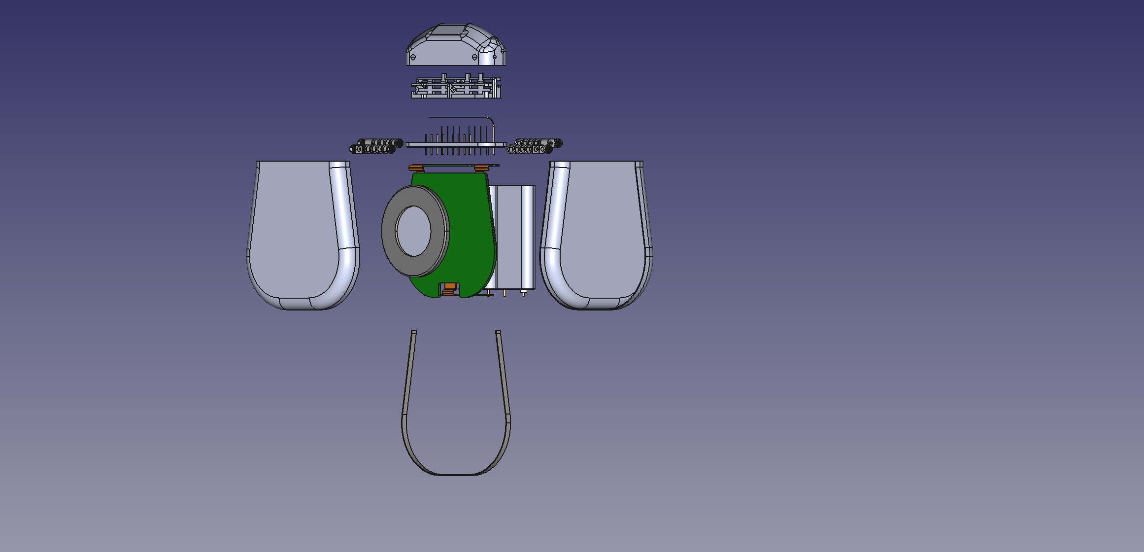
Exploded view of IPG.
What it is
The IPG provides current-based bipolar electrical stimulation, records biosignals using built-in analog front ends, and can connect to third-party sensors over an in-body I2C network. It communicates with a controller over Bluetooth Low Energy (BLE) and can be charged inductively. Two microcontrollers are used: an nRF52810 for BLE, and an STM32 ("MCU") for most other functions. (source)
Two PCB revisions exist with different channel counts and stimulation capability. Each has its own maturity, evidence, and BOM/fab-notes page — see Gen1 vs. Gen2 below. Currently, only the Gen2 PCBA is under active development.
The Gen2 PCBA is also available as a bench-friendly development board — the same hardware, retained in its manufacturing frame with USB-C power and breakout connectors, rather than trimmed down for implantation.
Gen1 vs. Gen2
| Gen2 PCBA | Gen1 PCBA | |
|---|---|---|
| Stimulation channels | 2 fully independent bipolar (square wave to 1200 Hz, or low-frequency sine wave) | 8 pseudo-independent monopolar |
| Biosignal AFEs | 4 differential (ECG/EMG/eCAP) | 2 differential (ECG/EMG/eCAP) |
| MCU firmware | Gen2 PCBA/FW-MCU-H2/ — revision-specific |
Gen1 PCBA/FW-MCU-H1-251201.hex — revision-specific |
| BLE firmware | FW-BLE/ — shared between versions |
|
| Design files released | Altium source files (schematic & layout), BOM, STEP | Altium schematics & layout, BOM, assembly drawing, fabrication drawing, test-point deck |
Both revisions share the same enclosure family (versioned independently, last release rev 0.7 — see either revision page) and the same BLE firmware. Note: as of March 2026 Windows control software backwards compatibility has now been broken; work would be needed to restore compatibility with Gen1 IPGs.
Maturity
Evidence E2 Acute in vivo
Manufacturing readiness M3 GMP-capable
Maturity levels refer to the packaged IPG. For maturity levels when using the PCBA as a development board, see Gen2 PCBA maturity and Gen1 PCBA maturity.
Standing disclaimer
These levels describe testing history and documentation state. They are not regulatory clearance and not a safety endorsement.
Control Software
Two software platforms exist for sending control signals to and streaming data from the OpenNerve IPG. The Windows app is under active development and is used for research across multiple working groups. The Android app has only been used for design verification testing, and is not considered mature.
- Windows app — see Windows software page.
- Android app, in development — see Android software page. Both require an encryption key exchange with the IPG firmware; contact open.nerve@usc.edu for the shared development key, or use the encryption guide (linked below) to generate your own. (source)
Charging
The IPG can be charged inductively using the OpenNerve Charger.
IPG Documentation
Design History Files
Design Output Review
Mechanical Specifications
Test Plan
Mechanical Design Images
DVT Protocols
Docs/Testing-Protocols/ contains eight PDFs, each named "Hornet IPG … DVT
Protocol". Each viewer below fetches its PDF live from the repo's default
branch — click a title to expand it:
Accelerated aging DVT protocol
Drop & impact DVT protocol
Heating during normal operation DVT protocol
Hermeticity DVT protocol
Minor mechanical shock DVT protocol
RGA DVT protocol
Shear force DVT protocol
Vibration mechanical force DVT protocol
Documentation synced from the upstream repo
The following documentation is available in the IPG's repository and has been mirrored here for convenience. Please submit pull requests for edits in the original document, not on this website!
For hands-on setup and usage instructions (power-up, the Windows control app, stimulation and recording workflows), see the Windows app's synced Getting started guide.
- MCU flashing guide
- BLE flashing guide
- OTA firmware update guide
- Logging guide
- Magnetic switch guide
- Encryption instructions
- Charging (CAR-212)
- WPT implementation report
- Impedance measurement strategy
- Tools: sine wave generator — bench tool for
testing neuromodulation hardware, from the repo's
Tools/directory - Tools: OTA updater user guide — CLI tool for
wireless Gen2 firmware updates over BLE, also from
Tools/