OpenNerve development board
Repo: CARSSCenter/OpenNerve-Implantable-Pulse-Generator — same hardware and firmware as the Gen2 PCBA
Not approved for human use
Nothing described on this page has regulatory clearance for human use. See Regulatory status and disclaimers. The board is suitable for bench work and non-human research use only — see What you can do with it below.
What it is
The development board is a genuine OpenNerve Gen2 PCBA, retained inside its manufacturing frame rather than trimmed down for implantation. The frame brings every signal that would otherwise be inside an implanted enclosure out to accessible connectors: USB-C for power and control (no battery required), 2 mm banana connectors on each of the 16 feedthrough contacts, and header pins for both onboard microcontrollers. This is the same PCBA described on the Gen2 PCBA page — nothing about the electronics is different, only what surrounds them.
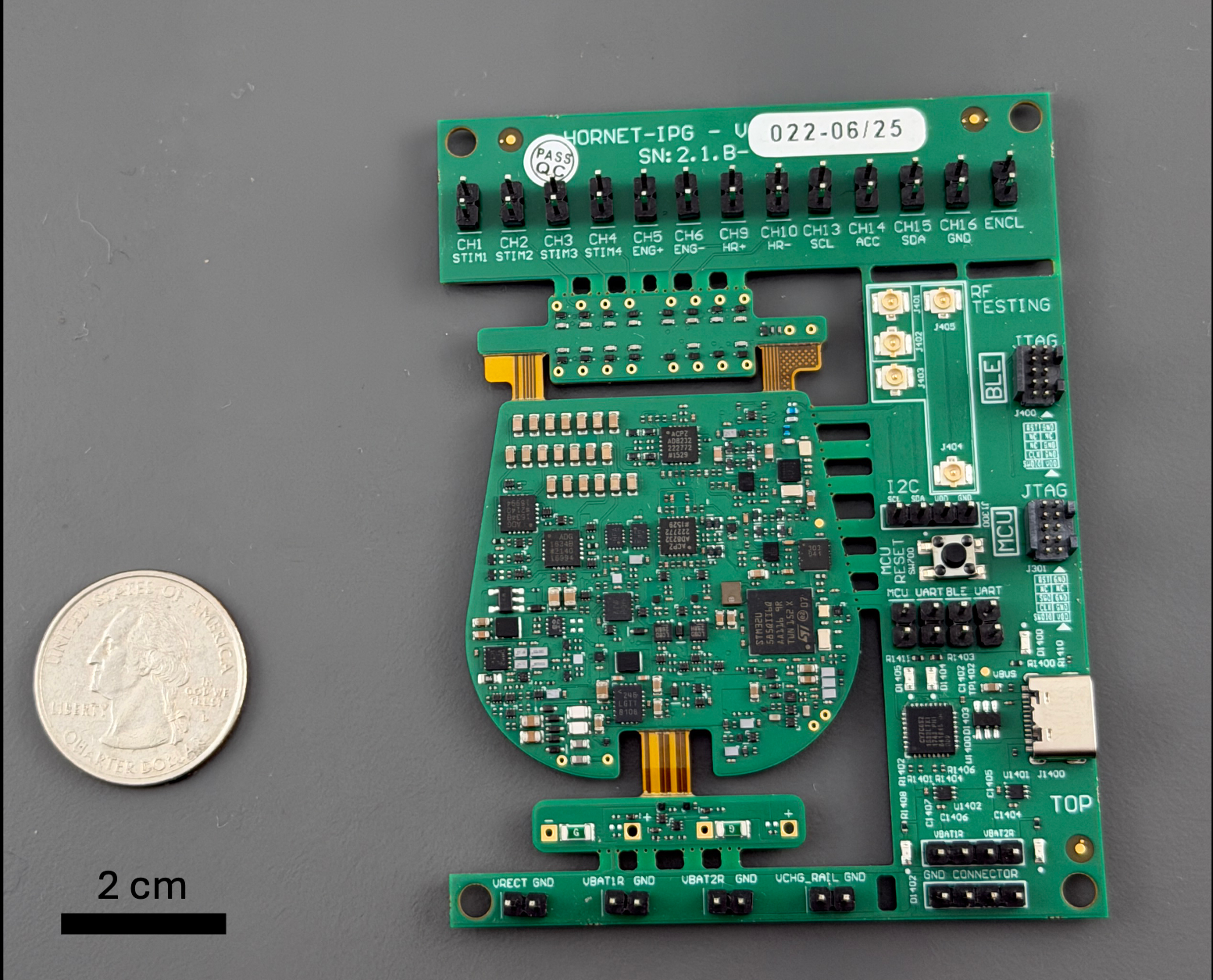
Gen2 dev board, with headers for stimulation, recording, and I2C communication as well as USB-C for power and communication.
What you can do with it
Everything below applies to the actual, sourced Gen2 hardware and firmware documentation already on this site — the development board is simply the form factor that gets you access to it on a bench:
- Stimulation and impedance measurement — set square-wave (to 1200 Hz) or low-frequency sine-wave (1-15 Hz) stimulation parameters and read channel impedance from the Windows control app. See the synced Getting started guide.
- Biosignal recording — two of the four configurable analog front ends (AFEs) are exposed as header pins for easy ECG, EMG, or eCAP/ENG recording; filter, gain, and sampling-rate figures for each are in the Getting started guide.
- Firmware development — flash the STM32 MCU firmware or the shared nRF52810 BLE firmware directly over JTAG/SWD. See the MCU flashing guide and BLE flashing guide.
- Over-the-air firmware updates — push a new firmware image over BLE without a wired connection. See the OTA firmware update guide. Powering the board from USB disables the magnetic switch, so waking it after an OTA update uses the reset button instead — noted in that guide. (source)
- On-device log capture — download and clear logs recorded internally by the IPG firmware. See the Logging guide.
- Third-party digital sensors — the board's I2C port supports the AMS motion-sensing lead today, and is open to other digital sensors under development. See Standard Leads.
Specifications
Stimulation and AFE (analog front end) specifications for the Gen2 PCBA, as sourced in the OpenNerve IPG flyer (internal document, not yet published to a public repo — see the note below).
Stimulation parameters
| Stimulation parameter | Minimum | Maximum | Step |
|---|---|---|---|
| Amplitude, mA | 0.2 | 5 | 0.1 |
| Pulse width, µs | 100 | 800 | 50 |
| Frequency, Hz | 1 | 1200 | 1 |
| Output limits, V | 0 | 11 | — |
| Ramp up/down duration, s | 0 | 10 | 1 |
| Train on/off duration, s | 10 | 300 | 10 |
AFE specifications
| AFE specification | ECG HR | ECG RR | eCAP | EMG |
|---|---|---|---|---|
| High-pass filter, Hz | 0.5 | 0.09 | 7.97 | 0.4 |
| Low-pass filter, Hz | 83.8 | 0.73 | 1,750 | 665 |
| Amplitude min LSB, ±µV | 2.8 | 2.8 | 0.37 | 1.4 |
| Amplitude max at 14 bit, ±mV | 24 | 24 | 3 | 48 |
| Gain for ADC Vref = ±3V | 125 | 117 | 1,005 | 250 |
| Recommended ADC freq., Hz | 256 | 256 | 6,400 | 2,560 |
ECG: electrocardiography. RR: respiratory rate. eCAP: evoked compound action potential.
How to get one
Development boards can be manufactured using the open source PCBA files available in the repository, or procured directly from OpenNerve (contact Open.Nerve@usc.edu to ask about availability).
Documentation
- Getting started
- MCU flashing guide
- BLE flashing guide
- OTA firmware update guide
- Logging guide
- Gen2 PCBA — the underlying hardware this board carries